
BESS for EV Charging: How to Retrofit Your First Battery—and Scale to Your Second—Without Vendor Lock-In
Grid connection capacity is becoming a major constraint on high-power EV charging deployment. While adding battery storage lets charging sites deliver megawatt-scale power from constrained transformers, the real engineering test begins when integrating existing chargers—or adding a second battery two years later. Here is how a vendor-neutral Energy Management System (iEMS) turns isolated hardware into a scalable charging microgrid.
The Grid Bottleneck: Why Buying the Battery Is Only Half the Battle
News suggests that properly sized battery storage can cut required grid connection capacity by 50% to 80% without compromising charging speed, helping Charge Point Operators (CPOs) and fleet depots avoid multi-year Distribution System Operator (DSO) upgrade queues and the steep costs associated with higher-capacity grid connections.
However, EPC contractors and site owners quickly discover a hard truth during commissioning: buying a site-level BESS does not automatically solve grid constraints. The missing layer is coordination. Between the utility meter at the Point of Common Coupling (PCC), the rooftop solar inverters, the Power Conversion System (PCS), and the DC fast chargers sits the Energy Management System (EMS).
Whether you are retrofitting a first battery onto an existing charging station (Phase 1: 0 to 1) or adding a second battery cabinet several months later to keep up with rising utilization (Phase 2: 1 to N), the architecture of your EMS plays a critical role in whether your transformer trips, whether your hardware stays locked to a single supplier, and whether your financial model survives rapid battery cycling.
Phase 1 (0 to 1): Retrofitting the First BESS onto a Constrained Charging Site
When stepping from "grid-only" to "grid + BESS" (0 to 1), site operators face three immediate operational hurdles that basic cloud-only software cannot handle:
1.Sub-Second Overload Prevention Cannot Rely on the Cloud
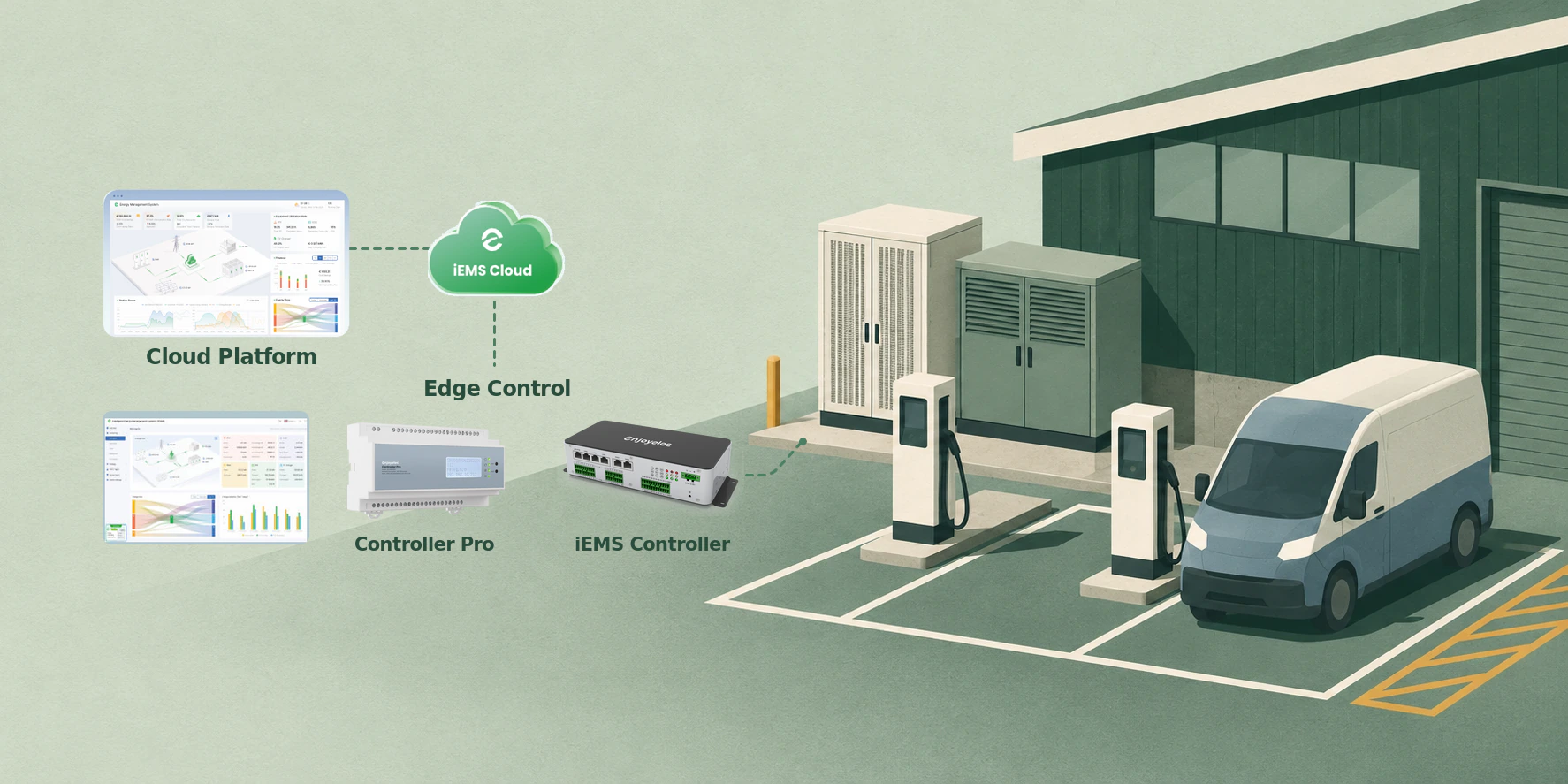
To prevent transformer overload, enjoyelec iEMS splits intelligence between the physical edge and the cloud:
-
Hard Real-Time Edge Control: An on-site industrial controller (Controller Pro or iEMS Controller) wired directly to the PCC meter, BESS, and EV chargers executes real-time peak shaving, overload prevention, and load balancing locally. If the battery's State of Charge (SOC) runs low during an extended peak, the edge controller immediately throttles and balances charger output dynamically to keep grid draw strictly below the breaker limit.
-
Offline Safety Fallback (Local Strategy & Local Platform): If internet connectivity drops during a storm or network outage, the edge controller automatically takes over using cached 24-hour cloud schedules or local safety presets. Field engineers retain uninterrupted real-time visibility and manual dispatch control via the on-site local platform.
2. Balancing Dynamic Tariffs Against Guaranteed Fleet Schedules
On the enjoyelec iEMS Platform, cloud AI combines precise tariff management with operational hard constraints:
-
Dynamic Tariff Optimisation: The platform ingests live pricing curves from major European energy suppliers alongside solar and load forecasts, automatically charging the BESS during off-peak or negative-price windows and prioritizing solar self-consumption.
-
Gantt-Style Dispatch with Hard Constraints: Operators can schedule daily operating modes via an intuitive Gantt-style timeline while locking in independent power limits, grid capacity caps, and minimum SOC thresholds for every schedule block. That guarantees the battery is at 90% SOC before evening fleet arrivals while still capturing dynamic tariff savings earlier in the day.
3.Auditing Actual ROI Through Performance Validation
Phase 2 (1 to N): Why Expanding BESS Capacity Later Breaks Traditional EMS Setups
This "1 to N" expansion is where many CPOs and EPCs hit a wall:
-
The Vendor Lock-In Trap: Most Phase 1 BESS installations rely on a proprietary EMS bundled by the original battery manufacturer. Two years later, when battery prices have dropped or a different OEM offers better lead times, the site owner discovers that the Phase 1 EMS refuses to communicate with a third-party Phase 2 battery.
-
Control Fighting: If an EPC installs a second battery with its own separate controller on the same grid connection, both systems read the same PCC meter independently. Without a single coordinating brain, Battery A may discharge at full power to shave a charging peak while Battery B mistakes the reduced grid draw for spare capacity and starts charging—wasting energy in a parasitic loop.
-
Degradation Mismatch: Pairing a two-year-old LFP battery at 84% State of Health (SOH) with a brand-new battery at 100% SOH requires state-aware load sharing, not blind 50/50 power splitting.
How enjoyelec iEMS Makes “1-to-N” BESS Expansion Plug-and-Play
| Expansion Challenge | Proprietary / OEM-Bundled EMS | enjoyelec Vendor-Neutral iEMS |
|---|---|---|
| Hardware Procurement | Locked into Phase 1 battery brand | Compatible with 100+ brands of BESS, PV, and chargers |
| Multi-BESS Coordination | Separate controllers risk fighting at PCC | Unified dispatch across old and new BESS cabinets |
| Adding New Assets | Requires custom PLC recoding | Drag-and-drop via Visual Topology Builder |
| Port & Interface Headroom | Often maxed out after Phase 1 | Up to 10× RS485, 3× CAN, 18× DI / 12× DO on iEMS Controller |
| Revenue Stacking | Limited to basic local peak shaving | Dynamic tariffs, V2G interaction, and VPP readiness |
-
Manufacturer-Independent Integration (100+ Brands) via Device Object Modeling: enjoyelec abstracts complex vendor protocols into standardized device object models with open Read/Write permissions and custom telemetry mapping. Whether Phase 1 uses Brand A inverters and Brand B chargers, and Phase 2 adds Brand C liquid-cooled BESS cabinets, the controller treats them as a single coordinated resource pool—allocating charge/discharge commands based on real-time SOC, SOH, and thermal limits.
-
Visual Topology Builder (Zero-Code Reconfiguration): When adding a second BESS or a new bank of chargers, field engineers do not need to rewrite firmware. Using enjoyelec's drag-and-drop visual topology builder, EPCs visually construct the updated electrical single-line diagram on a canvas, define the hierarchy between the main PCC meter, sub-meters, BESS units, and EV chargers, and push the updated control logic to the edge in minutes.
-
Future-Proof Hardware Sizing (Controller Pro vs. iEMS Controller): To prevent physical port shortages when scaling from a single cabinet to a multi-megawatt hub, enjoyelec offers two industrial edge controllers tailored to site growth trajectories:
| Specification | enjoyelec Controller Pro | enjoyelec iEMS Controller |
|---|---|---|
| Target EV Site Profile | Compact fast-charging sites, single-BESS retrofits | Large charging hubs, fleet depots, multi-phase BESS expansions |
| Mounting & Dimensions | DIN Rail (TS35), 158 × 87 × 60 mm | Rack Mounting, 235 × 114 × 55 mm |
| Serial & Bus Interfaces | 4× RS485, 1× CAN | 10× RS485, 3× CAN (built for multi-cabinet expansion) |
| Digital I/O (Breaker/Fire) | 5× DI / 5× DO | 18× DI / 12× DO (supports complex safety & switchgear interlocks) |
| Network Interfaces | 1× WAN (100M RJ45), Wi-Fi, Zigbee 3.0, BLE 5.0 | 2× WAN + 4× LAN (Gigabit RJ45), Wi-Fi, Optional 4G/5G |
| Supported Protocols | Modbus TCP/RTU, Zigbee 3.0, P1, TIC, SG Ready, Local API | Modbus TCP/RTU, SG Ready, Industrial Ethernet |
| Operating Temp & Rating | -30°C to 50°C, IP20 | -40°C to 70°C, IP40 (outdoor cabinet & harsh depot grade) |
Beyond Peak Shaving: Turning High-Cycling Storage into a Multi-Stream Asset
With enjoyelec iEMS, site owners can monetize every available kilowatt-hour across the asset's lifecycle:
-
Virtual Power Plant (VPP) & Grid Services: Idle BESS capacity and flexible EV charging loads can be pooled into Virtual Power Plants to participate in frequency regulation, demand response, and local DSO flexibility markets.
-
Dynamic Grid Feed-In Control: For charging hubs paired with large solar canopies, iEMS enforces gradient feed-in limits—storing surplus solar in the BESS first, routing it to plugged-in EVs second, and curtailment-free exporting only within utility-approved thresholds.
-
Optimized V2G (Vehicle-to-Grid) Readiness: For fleet depots where electric trucks or buses park for predictable windows, iEMS supports bidirectional energy orchestration between EVs, chargers, BESS, and the grid—turning parked fleet batteries into secondary buffers alongside stationary storage.
Frequently Asked Questions: BESS & EMS for EV Charging Sites
How much grid capacity can a BESS save at an EV fast-charging station?
A properly sized BESS paired with an intelligent local EMS can reduce the required grid connection capacity by 50% to 80% compared to a grid-only charging station. For example, a site running four 350kW DC fast chargers (1.4MW peak demand) on a 100kW grid connection can use a 1.3MW / 500kWh+ BESS to buffer peak hours without throttling drivers or waiting years for utility transformer upgrades.
Can I add a different brand of battery storage to my EV charging site later?
Yes—provided your site uses a vendor-neutral EMS rather than a closed OEM controller. Using Device Object Modeling and open protocols (Modbus TCP/RTU, CAN, Local APIs), enjoyelec iEMS integrates over 100 brands of BESS, solar inverters, and EV chargers. This allows EPCs and CPOs to add second-phase or third-phase battery cabinets from different manufacturers—or even integrate second-life EV battery systems—under one unified dispatch strategy.
What happens to an EV charging station if the EMS loses internet connection during peak load?
Cloud-only energy management systems risk transformer overload or breaker trips if cellular connectivity fails during peak EV charging. enjoyelec iEMS prevents this through Cloud-Edge Collaboration: the on-site Controller Pro or iEMS Controller executes millisecond-level overload prevention and peak shaving locally at the edge, automatically switching to cached 24-hour schedules or local safety fallback rules while keeping the on-site Local Dashboard live for field engineers.